Spider Robot Assembly Instruction Manual
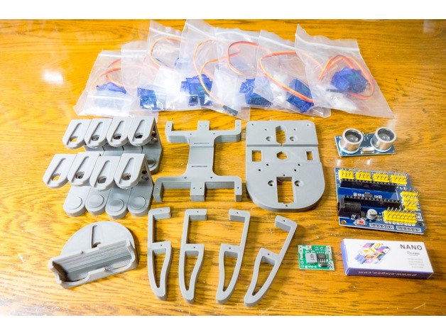
Once the above 3D printed parts and electronic parts are ready, it will be assembled.
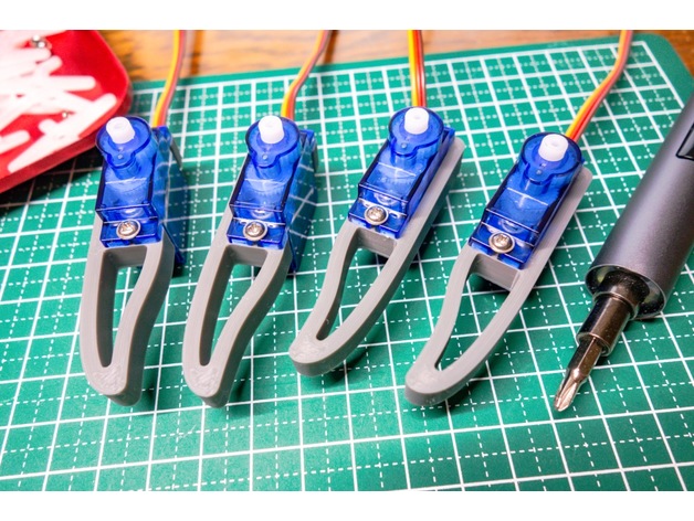
First, attach the servo motors to the left and right arms.
Please judge the left and right arms by the screw holes for attaching the servos.
Please use the screw attached to the servo for installation.
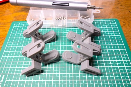
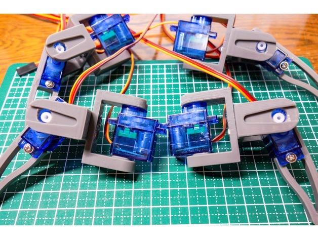
Next, make four center arms.
Since the shape is twisted 90 degrees, it is difficult to support when outputting with a 3D printer, so the parts are divided into parts that can be used in common on the left and right. Fix two diagonally each with
M3×6 screws and M3 nuts .
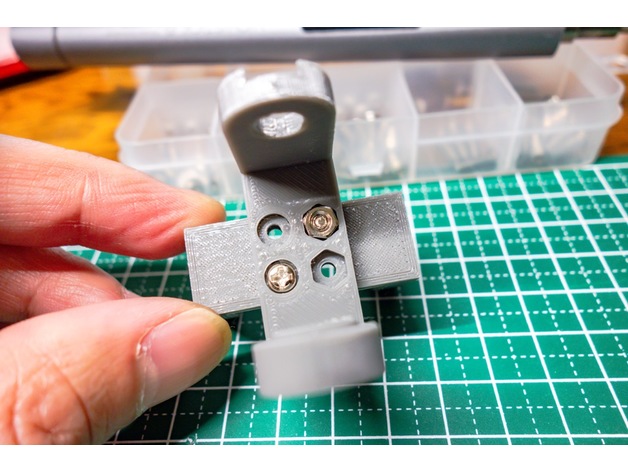
Please note that the direction changes from left to right!
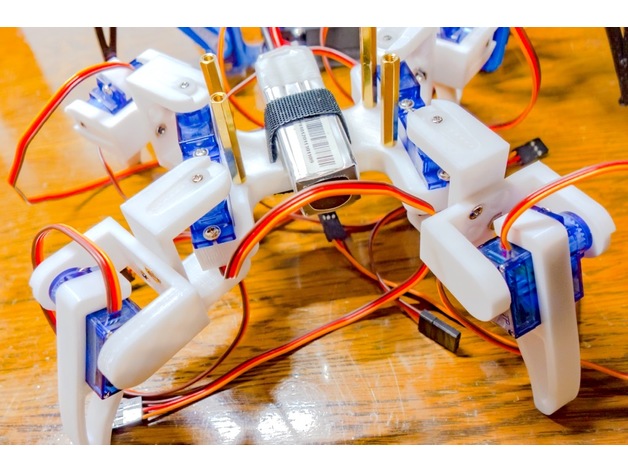
Install two servos symmetrically on the left and right as shown in the photo below.
Attach 4 servos to the body parts and place the arm as shown in the photo below.
The front legs and back legs are reversed (attaching the arms in the same direction diagonally), but this is simply because the sample program I made is made in this direction.
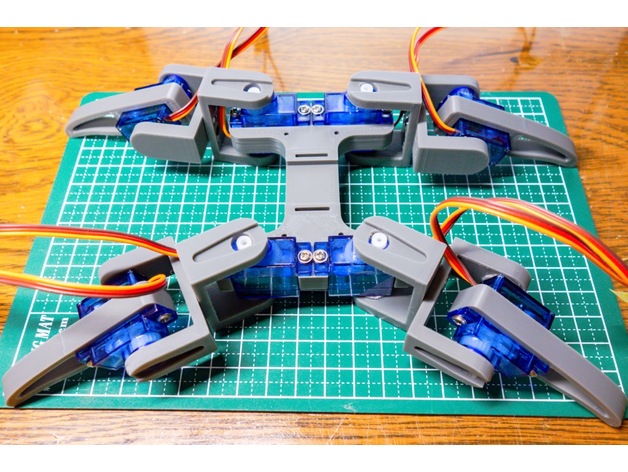
From here, attach the servo horn and fix the arm, but fix it at a position where the neutral (center position) of the servo motor is straight as shown in the photo below .
Also, use an Arduino to mount the servo horn with the servo fixed at the 90° position.
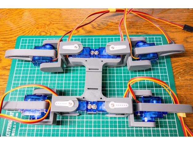
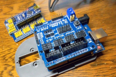
Next, attach four M3 x 20 male spacers to the body .
A 3mm hole has been made for the M3 shape, so it may be a little difficult to insert as a printed part, but please insert it while turning it with pliers or the like. (You may change to an insert nut!)
The center of the body is the battery space.
There is a hole through which Velcro with a width of 13mm is passed, so use this to fix it.
This time I used a lipo battery for drones.
It is smaller than a dry battery or a mobile battery, and can take out a higher voltage depending on the number of cells.
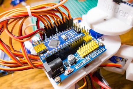
The Arduino sensor shield used this time can supply 5V voltage to the Arduino and servo motors by applying a voltage of 7 to 12V to the DC jack.
Prepare a battery within this range, or use a DC-DC converter for a battery with a voltage higher than this.
Since I have a 3-cell or 4-cell battery for the drone, I use a DC-DC converter to drop it to 5V and power it directly to the Arduino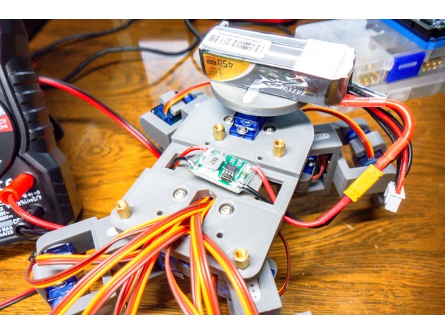
Next, attach M3 x 6 male spacers to the 2 parts of the body to fix the Arduino. (It doesn't matter if it's long)
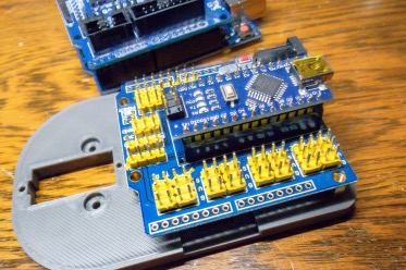
Since the sample sketch can be operated in common with Arduino Uno, you can mount the sensor shield for Uno on Arduino Uno in the same way.
For Arduino sensor shields, please refer to here!

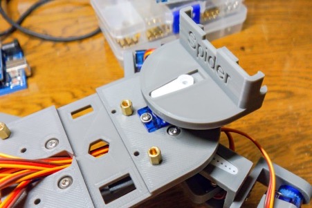
Next is the installation of the neck servo.
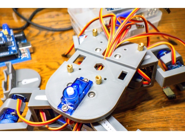
Install as shown in the photo below, and install the HC-SR04 mounter so that the center position is also the photo below.
Please arrange the wiring neatly.
At that time, it is a good idea to mark the wiring of the servo so that it is easy to understand.
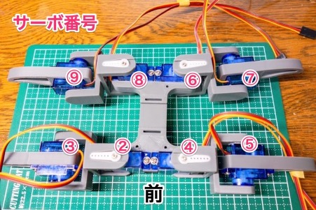
Allocate the servo numbers like this.
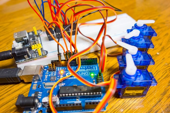
Lastly is the wiring.
Attach the servos to the digital terminals in the order of the assigned servo numbers.
Servo number 2 → pin D2
Servo number 3 → pin D3
Servo number 4 → pin D4
Servo number 5 → pin D5
Servo number 6 → pin D6
Servo number 7 → pin D7
Servo number 8 → pin D8
Servo number 9 → pin D9
Neck servo → pin D10
The ultrasonic sensor HC-SR04 connects the Echo pin to D12 and the Trigger pin to D11 pin, and Vcc and GND connect to the remaining digital pins to supply power.
Connect the Above-Mentioned Pins D2 to D9 on the Arduino IO Shield in the Order Given.
HC_SR04 ULTRASONIC SENSOR WIRING to the Arduino IO Shield
TRIGGER Pin 11
ECHO Pin 12
5V Pin to any 5V Pin on Arduino Nano IO Shield
GND to any GND Pin on Arduino Nano IO Shield
Battery Input needs to be connected to the VIN and GND PINS on Arduino IO Shield


")
")

")